 |
This is a good waveform |
 View larger image View larger image
 Download this waveform file for use with PicoScope Download this waveform file for use with PicoScope
Primary Ignition Waveform Notes
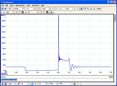
The ignition primary is looking at and measuring the readings seen on the negative side of the coil. The earth path of the ignition coil can produce over 350 volts. Within the picture there are several sections that need closer examination and is therefore important to select the correct voltage scale.
In the illustration shown, the horizontal voltage line (primary Sparkline) in the centre of the oscilloscope is at fairly constant voltage of approximately 40 volts, which then drops sharply into what is referred to as the ‘Coil Oscillations’. The length of the afore mentioned line is the ‘Spark Duration’ or ‘Burn Time’, which in this particular case is 1 ms.
The coil oscillation should display a minimum number of 4 - 5 peaks (both upper and lower) should be seen. A loss of peaks on this oscillation shows that the coil needs substituting for another of comparable values.
There is no current in the coils primary's circuit until the dwell period, when the coil is earthed and the voltage seen is drops to zero volts. The dwell period is controlled by the ignition amplifier and the length of the dwell is determined by the time it takes to build up to approximately 8 amps.
When this pre-determined current has been reached, the amplifier stops increasing the primary current building the current and this is maintained until the earth is removed from the coil, at the precise moment of ignition.
The high vertical line at the centre of the trace is over 200 volts, this is called the 'induced voltage'. Further information is available on the example ‘Induced Voltage’ waveform.
All these sections of the primary trace are also illustration in individual waveforms listed in the menu. The coil’s High Tension (HT) output will be proportional to the induced voltage. The height of the induced voltage is sometimes referred to as the primary peak volts.
A low (0 - 50) voltage scale is required to observe the sparkline and the coil oscillation, while a higher voltage of 0 - 400 volts will require the to check the induced voltage.
汽车诊断 | 汽车诊断仪 | 汽车故障诊断仪 | 汽车测试仪 | 汽车分析仪 | 汽车诊断示波器 | 汽车电路测试仪 | 汽车电路分析仪 | 发动机分析仪 | 发动机综合分析仪 | 发动机检测中心 | 点火分析仪 | 点火测试仪 | 汽车传感器测试仪 | CAN总线示波器 | LIN总线示波器 | 汽车故障记录仪 | 汽车传感器分析仪 | 汽车检测仪 | 喷油嘴测试仪 | 点火线圈测试仪 | 蓄电池测试仪 | 发电机测试仪 | 起动机测试仪 | ABS传感器测试仪 | ECU测试仪 | ECM测试仪 | 进气真空/压力测试仪 | 排气压力测试仪 | 汽车技术培训 | 爆震传感器测试仪 | 缺火测试仪 | 缺缸测试仪 | 线路测试仪 | 引出线 | 汽车数字示波器 | 真空传感器 | 高压感应测试头 | 无分电器点火测试头 | 独立点火(COP)感应测试头 | 漏电测试仪 | 气缸相对压缩测试 | 电脑测试仪 | 发动机控制器测试仪 | 泄漏测试仪 | 荧光检漏 | 超声波检漏 | 汽车数字万用表 | 电流钳表 | 电流勾表 | 点火正时灯 |
